Vertical Grid Layout
Different to the horizontal grid, the vertical gridding is not too obvious but still as important as the horizontal grid setup. In Concept Design models (2.5D), the vertical grid is generated on-the-fly based on the model settings such as building heights. You can change the settings for the vertical grid setup at any time. In Full 3D models the vertical grid is as fixed once you have created the model. The only way to change it is to convert the model down to a 2.5D model (and loose all the extra 3D information), change the grid settings and then re-convert it to 3D. In short, when creating a 3D model you should think of the vertical grid setup in detail BEFORE you start editing the model.
Concepts of Vertical Grids
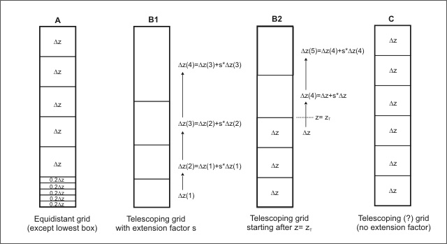
For the 3D Main Model, ENVI-met allows two different types of vertical grids: an Equidistant Grid (A), where all grids, except the lowest five, have an identical vertical extension Δz, and a Telescoping Grid (B1,B2 and C) where the grid size expands with the height. The figure below shows the differences the different types.

Different concepts for organizing the vertical grid layout: (A): Equidistant Grid, (B): Telescoping grid and (C): Telescoping grid with no extension factor
Remember that the resolution of your grid (horizontal as well as vertical) should match with the objects you have in your model. For example, it does not make sense to look at a very complicated building structure with overhanging building parts and small differences in building heights and then use a 5 m vertical grid. All of your fine structures will be reduced to a few single blocks!
Grid Version A: Equidistant
The equidistant grid has the same spacing over all vertical layers. Only the lowest box is split in 5 sub-boxes with Δzs=0.2 Δz. In the Area Input file, you enter the Δz for the non-split boxes.
This grid should be used if the model domain is of limited height and the processes in all heights are nearly of the same interest.
Grid Version B1 and B2: Telescoping
The telescoping grid allows to cover much more height without running out of grid points. This grid should be used if the model domain has high objects (e.g. skyscrapers) that should be included, but the processes at the upper parts of the model are of less interest.
In the Area Input File you specify the grid size of the lowest grid box above surface (with is not split into sub-boxes) and the percentage of increase to the next box (extension factor s).
The vertical grid size $\Delta z$ of a box $k$ can be calculated with
$$ \Delta z(k) = \left[ \left( 1 \frac{s}{100} \right) \right]^{k-1} \cdot \Delta z_{start} $$
where $s$ is the extension factor given in percent and $\Delta z_{start}$ is the user-defined grid size of the first grid box above ground in case of B1. You can also specify a given height from where the telescoping should start ($z_T$ in B2 in the figure above). All z-layers below this level will be spaced with a constant $\Delta z_{start}$, above $z_T$ the telecoping will start as described before.
The maximum increase is 20% because otherwise the 1D Model which extends to 2500 m height from the top of the 3D model won't fit!
Grid Version C: Telescoping, but without Extending
Although grid C was generated with the telescoping grid method, it is the least telescoping grid available. To generate a vertical grid without splitting the lowest box into 5 sub-boxes, use the telescoping grid method with an extension factor of s=0 ! Alternatively, you can use method B2 and set zT to a very high level not reached in the model.
What about the 1D Model?
In the range from the surface up to the height of the 3D model, the vertical layers of the 1D and the 3D model are identical.
Above the height of the 3D model, ENVI-met uses 14 additional layers in the 1D model to reach the height of 2500 m (which is set constant). The vertical size of these grid boxes are smoothly increasing with the height. The increase factor is calculated with respect to the actual height of the 3D model top.
Troubles & Annoyances
ENVI-met cannot find a Good Vertical Spacing between the Top of the 3D Model and 2500 m
This problem can occur when ENVI-met cannot find a possibility to squeeze the remaining 14 grids between the top of the 3D model and the top of the 1D model at 2500 m according the internal rules.
As a result, the model top will not be exactly at 2500, but a bit above or below that level, depending on the possible solutions.
Note, that ENVI-met will not use smaller grid cell sizes for the 14 grids in the 1D model than used in the 3D model.
Also, ENVI-met always looks for a smooth transition between the vertical grid sizes!
Normally, this is not a real problem an the simulation should work fine. However, you should check, where the top of the 1D model exactly ended in your case (see output).
← go back to Knowledge Base Index
See also: ()